马上注册,结交更多好友,享用更多功能,让你轻松玩转社区。
您需要 登录 才可以下载或查看,没有帐号?立即注册

x
PTGui有两个版本:PTGui和PTGui Pro。两者的最大区别是,后者有HDR高动态拼接、遮罩、视点矫正、暗角矫正、曝光矫正、白平衡矫正。本帖只隆重介绍对于全景补地帮助最大的“视点矫正”功能。
9 B# p1 N5 w! L" s- {* v
3 ^2 r8 P) Y# R8 ^5 |最直接、最简单一句话介绍的话,视点矫正,就是补地拍摄的照片,可以脱离该机位原有的镜头节点(视点)位置进行拍摄,然后在PTGUI软件里将视点的偏移矫正回来。
3 H- c* J1 J* r- X" t8 s" _( _6 B/ e" U, N
最重要的一句话要记住:视点矫正,仅对于二维平面景物有效!!!$ Y: `( i' \; k
/ A* |& v4 O! \4 L' g4 B9 c. P
; I, M7 y/ E; ^& l& J+ o, ^% |PTGui Pro的“视点矫正”功能详解(官网正文节选)
4 V. I; s H2 ^& K. M; v6 \李景超翻译并编辑
8 g% J" N( m% I- D3 d$ |& Z% k; P* `% ~( E
+ Q$ Y* b* V$ Q
由于“视点矫正”只对二维平面景物有效,所以,当要用到补地的图片时,这张图片应该只在地面上有控制点。如果软件在地面以外的地方加了控制点,则必须手动删除,并在地面需要的地方手动添加控制点。PTGui的“自动对齐”功能,不能判断某控制点是否在地面上。用较多分散的控制点(推荐至少10个)可以达到最好的效果,而控制点数量太少,或者控制点的分布太靠近了,都可能引起优化引擎的误判。
/ f# F2 z% l+ B+ t) j) a6 N, v
) k8 W+ Z. d+ z6 Y% p, \由于“视点矫正”只对二维平面景物有效,所以,当要用到补地的图片时,这张图片应该只在地面上有控制点。如果软件在地面以外的地方加了控制点,则必须手动删除,并在地面需要的地方手动添加控制点。PTGui的“自动对齐”功能,不能判断某控制点是否在地面上。用较多分散的控制点(推荐至少10个)可以达到最好的效果,而控制点数量太少,或者控制点的分布太靠近了,都可能引起优化引擎的误判。
1 y! y7 z. n7 Y" w3 ~示例: 以新加坡摄影师Raffles Quay的四张原始底片为例: 这里可以下载:http://www.ptgui.com/images/vptut/viewpointcorrection.zip
. z3 g, X0 H/ k# I$ S2 c启动PTGui,添加这4张图片(img_2619.jpg ~ img_2622.jpg),点击“对齐图像(Align Images)”。PTGui将分析这些图像,并自动添加控制点。 下边是结果(步骤一):
. q2 ?. O# \3 r% ] p
/ Y) f5 t! u# n0 y( n# P# a此例中,图像对齐的情况,可以通过编辑控制点进行修改。比如,删除PTGui自动设置在移动的白云上面控制点。另外,我们也可以大楼上和地砖上手工额外增加一些控制点,以得到更加分散到整个图像区域的控制点。在“优化”选项卡中,选择“最小的镜头畸变(Minimize lens distortion: Heavy+Lens Shift)”,可以得到很好的畸变矫正和少量圆形裁剪图像位移补偿。然后,按F5进行优化,可得到控制点平均距离为0.85的结果,效果非常好(步骤二)
2 D& |, i5 w! P: h- U8 ?5 e" M但是由于全景拍摄时,镜头稍上仰,导致上图在拼接后地面有一个黑洞,因此,要进行补地拍摄,作为修补黑洞的“补丁”:
+ B! n( U, t1 ~+ U% }# D5 ]" S! S
为了更好地演示PTGUI“视点矫正”功能之强大,补地的照片故意在较大的的视点位移下拍摄:相机被移到了距原机位至少1米的位置,相机高度也与原来不同。相机向原来的拍摄点下方的地面倾斜拍摄。这就是我们在论坛里经常提到的“斜拍补地”。 ( R9 o4 n! H' a
拖动那张补地图片(nadir.jpg)到PTGui窗口,添加到该项目中。然后按照如上所述,为补地图片手动添加控制点,并且所有控制点都必须在地面上。 使补地的一张图片分别与前面所有4张图片之间都有控制点(步骤三)
i, C* Z3 F9 l
; z+ \' J; a+ ^& w* D如果我们试着优化这个工程(按F5键),得到的结果非常糟糕“very bad”(步骤四): $ C& Y" I. c' @4 ?/ O' s- M7 C8 B
没有对齐的原因是补拍地面图片时相机有位移,这是PTGui传统图片对齐模式不能奏效的。但是我们使用视点矫正方式,如下: 在优化选项卡下按下“高级”按钮切换到高级优化模式。首先我们在地面图片没有控制点的情况下优化工程,没有视点位移的影响,让PTGui自己决定正确的滤镜参数。我们可以取消选择“use control points of image 4”(步骤五)
0 g/ Q) X8 I. }6 S# T8 ?5 A 按F5键运行优化程序;结果应该再一次是“Very Good”,前4张图片会和没有添加地面图片之前一样真正对齐。 现在再次让image 4的控制点起作用,同时为image 4启动视点优化程序(步骤六) ' ? V7 r6 l4 V3 i
* a$ a- o4 _5 z+ S9 r4 ^/ l' A( R( D# w% f/ K
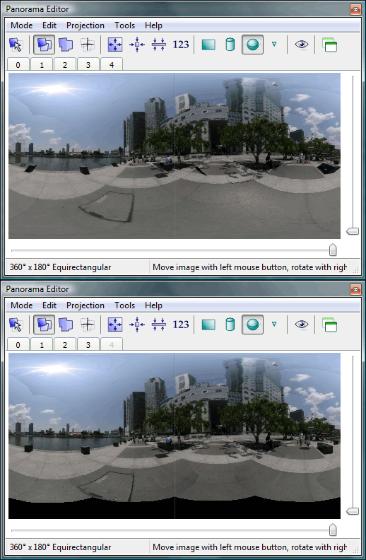
6 N; I, T9 l7 j' N 再次按下F5键运行优化程序。注意到即使地面图片也优化的情况下结果是“Very good”。下边是在“panorama editor”窗口中看到的对齐情况: ( J' }, b( c8 u2 Z. ?
; ~* _6 @0 D1 w; u* V
& ?( o# Q! H4 p$ {0 A. ]
& ^7 k$ i9 h5 N$ ]; M/ N
如我们看到的那样,尽管有视点的位移,地面这层的对齐效果几近完美。注意到不管是地面这层以上还是以下都没有对齐,比如那个黑色的方块就没有在地面层上:
* z6 I. o, Z. J% V% ^( y9 t4 [- e9 L" b8 f
这点很容易通过调整“Blend priority”参数解决。到“Image Parameters”选项卡中,减小地面图片的融合优先级,从100调整到25(步骤七)。这会是图片融合器仅仅使用地面图片中央的那部分(还加上一点额外的重叠)。参见PTGui“Image Parameters”选项卡的在线帮助得到更多信息。
5 I" x9 n- a& c+ i) S7 I: E得到完美的地面效果: http://www.ptgui.com/examples/BoatQuay/
; o* k4 p3 C) J3 o; T! S) [4 a! _6 i8 C, o5 m' S6 J
答疑: 在本地最小化状态下运行优化引擎时,得到“Very bad”的结果时有发生。原因是补地图片尚有大量的参数需要优化,而这些参数之间很多是互相关联的。你可以提供一个合理的开始点,来帮助优化引擎,具体步骤如下: 1、在“图片参数”选项卡中,将所有的VP值设置为0; 2、在“优化”选项卡中,屏蔽所有图片的视点矫正选项,选择所有图片“use control point of:”,运行优化。这会得到很糟的优化结果,但是可将补地图片放到适当的位置; 3、暂时取消补地图片的“use control points of”选项,不选视点矫正,运行优化。这次应该得到“Good”的结果,设置正确的镜头参数; 4、至此,优化引擎应该有了一个有效的起始点。复选地面图片的“use control points of:”和视点矫正选项,再次运行优化。
$ l* P7 @7 D8 i0 [3 b N, [如果优化引擎仍然报告“bad”的结果,按下边的步骤试一下: 1、设置补地图片的“pitch”到-90,“yaw”到0。重置补地图片的5个VP参数到0; 2、在优化选项卡中,屏蔽地面图片的yaw和pitch的优化选项,打开视点矫正,打开所有图片的“use control points of:”选项; 3、运行优化程序; 4、如果优化引擎报告“good”或“not bad”,优化引擎可能找到了补地图片的正确位置。现在打开补地图片的yaw和pitch优化选项,再次运行优化程序。
9 M2 s- O( |1 N: B" r. Z+ f如仍不见效,请重新检查补地图片的控制点,确认没有错点。注意,仅仅一错点就可能导致错误的结果。 9 V7 O) e: o! ]8 o! \7 b
/ _7 f5 D! Q/ [
6 E2 U4 \ ~% Z8 y/ q- U" ^
| 


